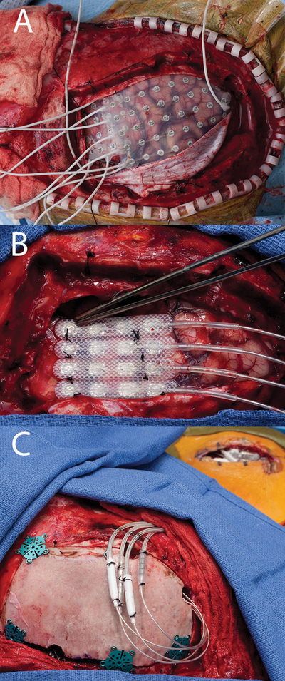
Figure 10:

a) Grid implant. b) final electrode configuration with resume 2 leads sutured together in a row of 4 placed over the test stimulation site. c) Implant with battery in place, notice the lead extension connectors in this circumstance are placed over the craniotomy, these are typically sutured down higher on the head in order for the patient not to have discomfort when laying on them. Further, the incision to the right of the field is the battery pocket. The lead extensions are typically tunneled behind the ear with the patient in pinions which requires thought in patient positioning.
