
Fig. 2. Single strut characterization.
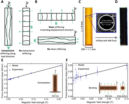
(A and B) Schematic illustrations of how the magnetic field application direction affects the stiffening of a strut. (A) In the axial case, a magnetic field applied transverse to the strut will produce no increase in axial stiffness, regardless of field strength applied. (B) In the bending case, a magnetic field applied perpendicular to the displacement will have no effect on bending stiffness, regardless of the field strength applied. (C) Side view optical image of the hollow polymer strut before infilling with MR fluid. Inset is a scanning electron microscopy micrograph of the hollow polymer strut cross section. (D) Side view optical image after infilling with MR fluid. The strut dimensions are 1.0-mm inner diameter (ID), 1.1-mm outer diameter (OD), 50-μm wall thickness, and 5-mm length (L). (E and F) Force-displacement slope versus magnetic field strength plots. (E) Uniaxial compression showing experimental results and model calibration. Inset is a schematic illustration of the experimental setup from the side view. (F) Cantilevered bending showing experimental results and model calibration. Inset is a schematic illustration of the experimental setup from the side and cross-sectional views.