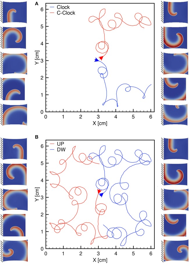
Figure 10.
(A) Clockwise (blue) and counterclockwise (red) tip trajectories obtained in a dynamic uniaxially stretched case with MEF parameters D1 = 0, Gs = 0.125 and initiated via the S1-S2 stimulation protocol. (B) Counterclockwise spiral initiation from top (red) or bottom (blue) boundary. Side panels show progressive spiral frames for the two cases.

