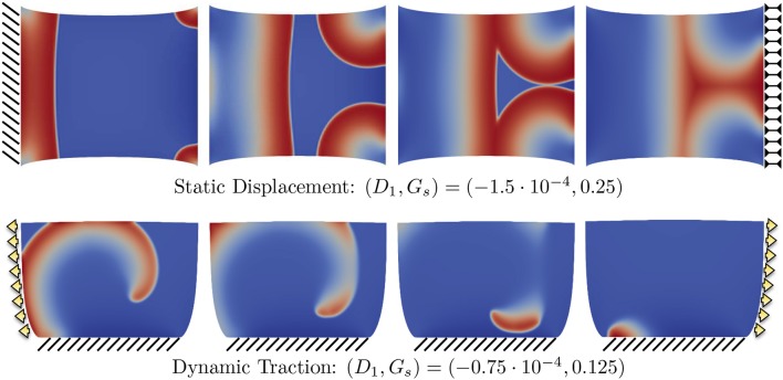
Figure 8.
Example of different propagation patterns according to different mechanical boundary conditions and parameter space. First row shows the uniaxial static displacement configuration for which the selected parameters induce additional activations from the corners of the domain due to the excessive level of SAC (Gs). Second row shows the dynamic traction configuration for which the initiated spiral wave goes through breakup due to the effect of mechanical loading.

