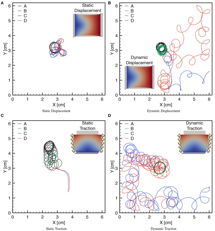
Figure 9.
Tip trajectories for four combinations of MEF parameters (D1, Gs) (see Table 3), applying static/dynamic–displacement/traction boundary conditions as indicated in the corresponding inset. Inset color code refers to the magnitude of the displacement field. (A) The last second of simulation is shown for the four cases with localized cores. (B) The last 3 s of simulations are shown highlighting the differences of the meandering. (C) Different times are shown for the four cases since for Gs > 0 the spirals exit the domain soon after initiation. (D) The last 3 s are shown for the case Gs > 0 highlighting the different meandering obtained with respect to Gs = 0. Minor discontinuities are due to the frame resolution for post processing analysis and are not linked to the accuracy of the numerical solution.

