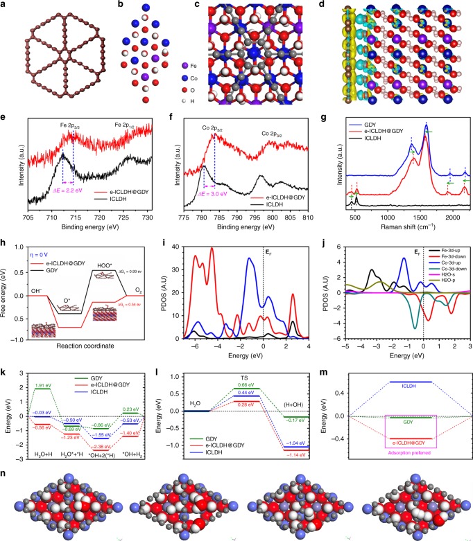
Fig. 5.
Theoretical calculations and structural analysis of the electrocatalysts. The stable configurations of a GDY, b ICLDH and c ICLDH@GDY. d Charge density difference for the stable configuration of ICLDH@GDY. e Fe 2p and f Co 2p core-level XPS spectra of the e-ICLDH@GDY/NF structure. g Raman spectra of GDY, ICLDH, and e-ICLDH@GDY; arrows indicate the directions of the shifts of the Raman spectral signals relative to those of e-ICLDH@GDY. h The free energy changes for the formation of OOH* and corresponding stable structures of GDY (ΔG1) and e-ICLDH@GDY (ΔG2). i PDOSs of the 3d and 2p bands of interfaced system containing GDY and ICLDH layers. j PDOSs of Fe-3d, Co-3d, H2O-s and H2O-p bands near the interface region. k Energetic pathway of HER under alkaline conditions for e-ICLDH@GDY, ICLDH, and GDY, respectively. l Comparison on the transition state barrier for H2O-splitting among three systems. m H-chemisorption of these three systems. n Structural evolution path for alkaline HER within e-ICLDH@GDY interface system

