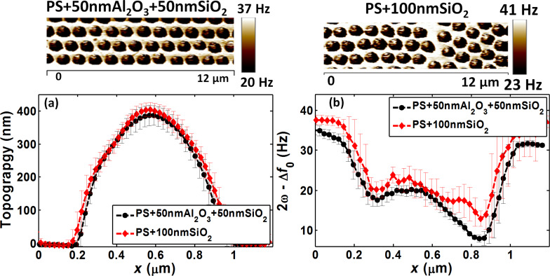
Figure 9.
Approach 3 (step B) PS + 50 nm Al2O3 + 50 nm SiO2 and PS + 100 nm SiO2 samples: (a) Average topography profiles, (b) average EFM signal profiles (lower panel) and the corresponding EFM images (upper panels). To avoid border effects, the EFM cross-sections were collected slightly far from the center and this is reflected by the change of the apparent particle width on the EFM average profiles.

