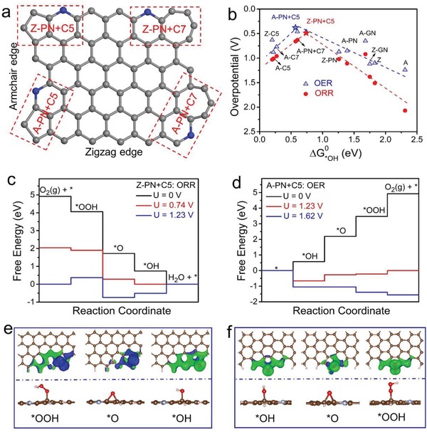
Figure 4.

a) A schematic graphene nanoribbon with four typical composite active sites. A: armchair edge, Z: zigzag edge, PN: pyridinic‐N, C5: pentagon carbon ring, C7: heptagon carbon ring. For example, the composite of pyridinic‐N and pentagon defect on the armchair edge is labeled as A‐PN+C5. b) ORR and OER volcano plots of overpotential versus adsorption energy of *OH (ΔG 0 *OH). c) Calculated Gibbs free energy diagrams of ORR and e) the optimized adsorption configurations of ORR intermediates (*OOH, *O, and *OH) on Z‐PN+C5 site. d) Calculated Gibbs free energy diagrams of OER and f) the optimized adsorption configurations of OER intermediates (*OOH, *O, and *OH) on A‐PN+C5 site.
