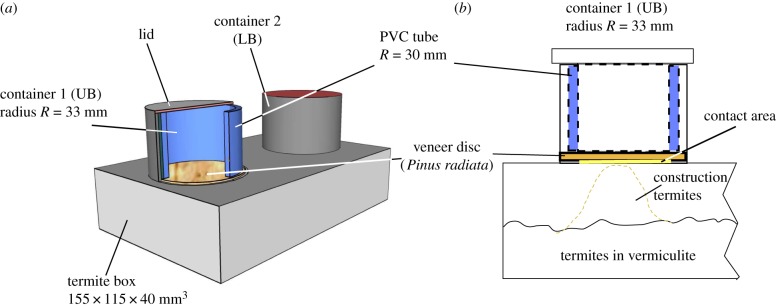
Figure 2.
Schematics of the termite box design. (a) Three-dimensional view on the termite box showing the UB veneer disc through the cut open view of the PVC tubing; (b) two-dimensional schematic: within the PET cylinder the PVC tubing is pushed onto the veneer disc; the termites build up material underneath the LB and UB side to reach the contact zone (radius 27 mm). (Online version in colour.)

