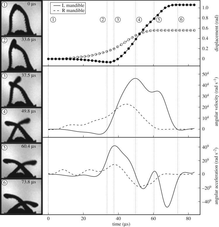
Figure 4.
Snap jaw kinematics. Left—Still images from a high-speed video of a representative M. camillae major worker mandible snap. The time elapsed since the beginning of mandible movement is given. Right—Kinematic profiles of the left (solid line) and right (dashed line) mandible derived from a high-speed video of a single mandible snap. Displacement (top panel) of the mandible tips (filled and open circles) was calculated from their x-y coordinates and smoothed with an interpolated spline. Angular velocity (middle panel) and angular acceleration (bottom panel) were calculated as the first and second derivative, respectively, of the smoothed displacement data. See main text for description of major events during strike and table 1 for means and variance across samples.

