Table 2.
Visual analysis of the 3D model changes that have occurred, along with the illustrations.
| No. | Illustration and Description |
|---|---|
| 1 |

|
| Both scans were superimposed on one another and formed into two interpenetrating mesh models. Using the compartments of two overlapped schemes, the state of change is visible in the course of a composite bridge span overloading. | |
| 2 |
|
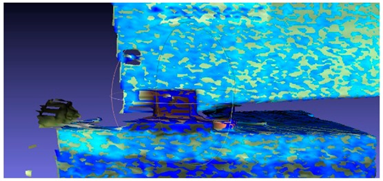
| Bridge span support region, where it can be seen that two mesh models penetrate each other in a uniform manner, indicating that this place shifted after the proof loading process. | |
| 3 |
|
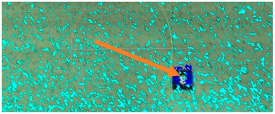
| Bridge span the middle-bottom region, where it is visible that the two mesh models interpenetrate in a homogenous way. This indicates that this place does not shift in the perpendicular direction, but it might be seen, by looking at signal placed to the bridge, that the surface has moved in the vertical direction by a small amount. | |
| 4 |
|
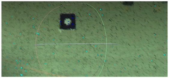
| Bridge span middle-bottom region, in which it is visible that the two mesh models do not interpenetrate, indicating that this place does not shift in the perpendicular direction. | |
| 5 |
|
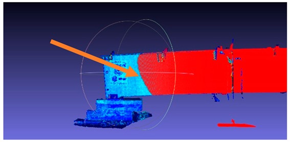
| On the illustration above the mesh model corresponding to the more deformed state is presented in red color. The character of the deformation is visible. Displacement of the side surface has occurred with tilting in the perpendicular direction, determined by the three-dimensional polyline in a parabolic shape. The deformation silhouette may indicate a place where increased stresses start to occur. The elliptical shape of the polyline is puzzling. We can explain it by the increased rigidity of the upper part of the lateral surface caused by the diaphragm lip, perpendicular to the plane of the shell, which closes the top. | |
| 6 |
|
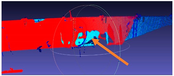
| Obstacles placed between the scanned object and a scanner device cause rifts in the point cloud structure. The breaches, so-called shadows, have been caused by people who passed through in front of the lateral surface of the bridge span during measurement. | |
| 7 |
|
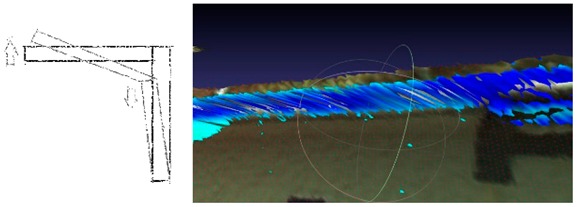
| The diaphragm lip of the bridge is subject to rotation. |
