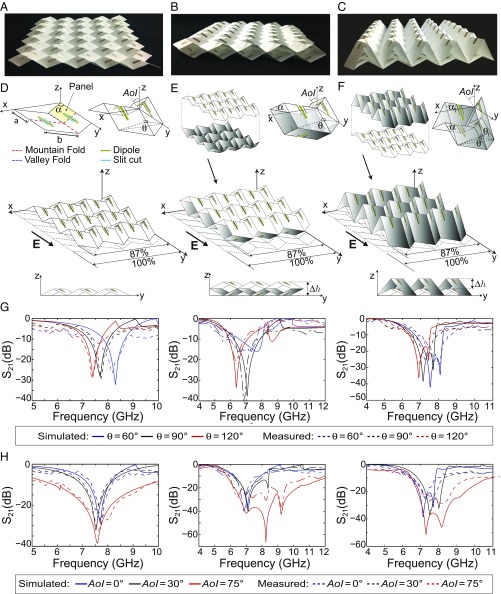
Fig. 1.
Design, assembly, and response of a proof-of-concept origami FSS assemblage with dipole elements of dimension 20 × 2 mm. Shown are prototypes of (A) Miura-FSS, (B) mirror-stacked Miura-FSS, and (C) inline-stacked Miura-FSS. (D) Miura-FSS unit cell with mm, , and its folded configuration with folding angle . (E) Assembly of two identical Miura-Ori layers into a mirror-stacked configuration and its unit cell. (F) Assembly of two Miura-Ori layers into an inline-stacked configuration and its unit cell, where the intrinsic geometry for the “white” unit cell is defined as mm, , and for the “shaded” unit cell as , , (see SI Appendix for details). (G) Frequency response in terms of transmission coefficient for the single-layer, mirror-stacked, and inline-stacked Miura-Ori assemblages for folding angles corresponding to panel extensions of 50%, 71%, 87%, respectively, and considering a normal angle of incidence (AoI) with a linearly polarized electric field E that is oriented along the length of the dipole elements. (H) Frequency response in terms of transmission coefficient for the single-layer, mirror-stacked, and inline-stacked Miura-Ori assemblages for folding angle (i.e., 71% extension) and AoI = .

