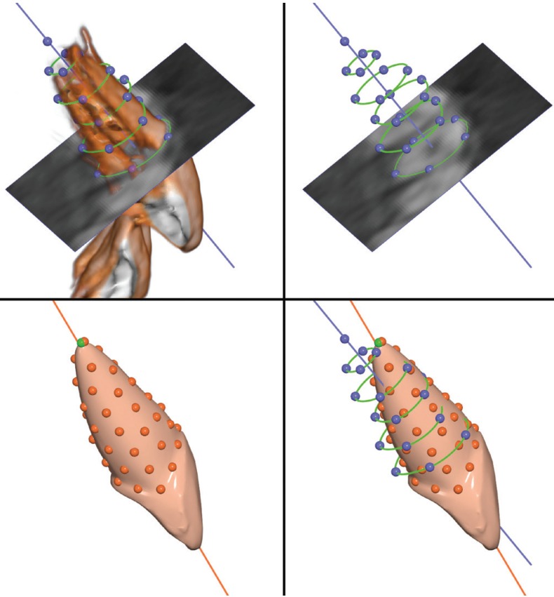
Figure 2.
Workflow for axes angle measurement. Upper left: Rendering of the upper central incisor from the CBCT image. The axial slice is shown here at the level of the cervix of the tooth, but could be repositioned along the long axis. Green curves show root outlines drawn on the slice at predefined positions. Blue line is the best-fit line to the blue landmarks, representing the long axis of the root. Upper right: The outlines were drawn on the slices as described in the text. Each outline had four or five equidistant landmarks. Lower left: The incisor with virtual constructed root, as imported from the Ortho Insight 3D® software. Fifty points have been placed uniformly over the root and the best-fit line to these points represents the virtual root axis. Lower right: The two axes superimposed. The depicted angle is approximately 8 degrees. All images from the Viewbox software.

