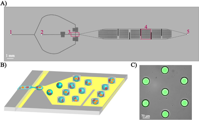
Fig. 1.

Microfluidic droplet trapping array. A) Top view of the device showing two inlets for carrier oil (1), cells and NPs in aqueous buffer (2), a flow-focusing junction (3), the droplet trapping array (4), and the single outlet (5). B) Schematic of the generation and trapping of individual droplet containing single cells and NPs. C) Overlay fluorescent microscopy image showing aqueous droplets containing the fluorescent dye 5(6)-carboxyfluorescein trapped in the device.
