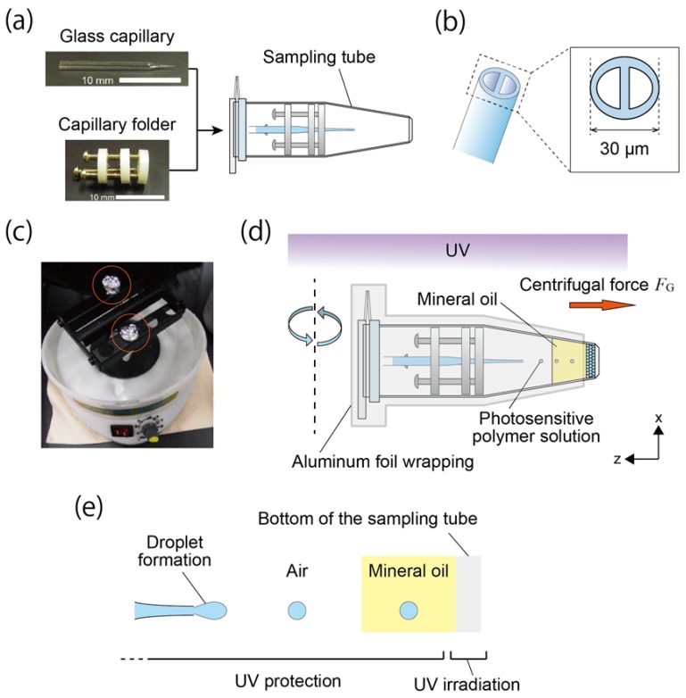
Figure 1.
Centrifuge-based microfluidic device and fabrication scheme of the honeycomb microhydrogel network. (a) Setup of the centrifuge-based microfluidic device. The microfluidic device consisted of the theta-shaped glass capillary, the capillary holder and the sampling microtube. (b) Illustration of the theta-shaped glass capillary. A partition exists inside the capillary. The orifice diameter was tuned to 30 μm. (c) The device in the centrifuge. The orange circles indicate the device wrapped by aluminum foil. (d) Schematics of the fabrication of the honeycomb microhydrogel network. The centrifugal force FG was applied to the assembled microfluidic device under UV irradiation from the top of the centrifuge. The honeycomb microhydrogel network was formed at the bottom of the sampling tube. (e) Formation and discharging of the droplet under the UV irradiation. Owing to FG, the photosensitive polymer solution in the glass capillary was dripped and discharged to the air phase. In the glass capillary, the polymerization of the photosensitive polymer solution was inhibited because of the partial protection of the UV irradiation.

