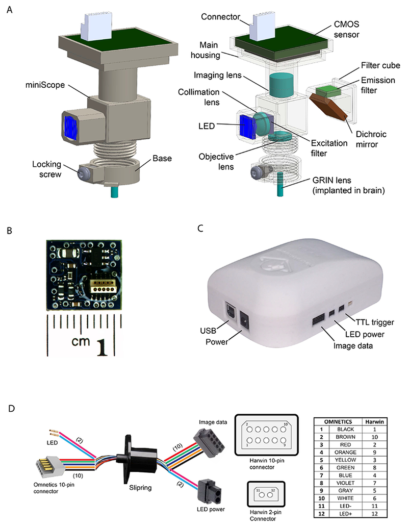
Figure 1.

(A) Illustration of the miniScope main body and base. Left: 3D model of the integrated miniScope and base mounting mechanism. Right: Individual components consisting of the miniScope, including CMOS sensor (with connector), imaging lens, excitation/emission filters, dichroic mirror, collimation lens, LED, objective lens, main housing, filter cube, base, and locking screw (nut). (B) Illustration of the CMOS sensor PCB board. (C) Illustration of the data acquisition controller. (D) Illustration of the construction of the data transmission cable.
