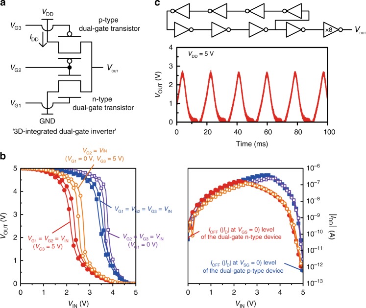
Fig. 5.
Stacked 2-T dual-gate devices. a Schematic circuit of the 3D-integrated dual-gate inverter (VG1, VG2, VG3: gate inputs, IDD: static current from the source). b Voltage transfer characteristics (left) and static currents (right) of the inverter operation according to the combinations of electrical gate connections. c Schematic circuit of the ring oscillator which is composed of seven 3D-integrated dual-gate inverters and its oscillation operation. The buffer output stage consists of serially connected two inverters, where the transistor W of the last inverter is designed to be eight times larger than that of the others

