Fig. 6.
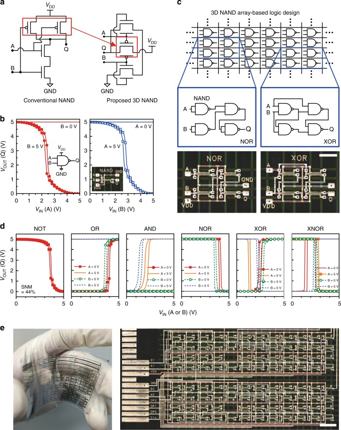
3D NAND digital circuit design based on stacked 3-T dual-gate devices. a Schematic circuits of a conventional NAND gate and a proposed 3D NAND gate. b DC VOUT–VIN characteristics of a 3D NAND gate. c 3D NAND array-based logic design (scale bar is 2 mm). d DC VIN–VOUT characteristics of a 1-input NOT gate and 2-input (A and B) logic gates (OR, AND, NOR, XOR, and XNOR) implemented by interconnecting 3D NANDs. A fixed voltage (0 or 5 V) is applied to one port while a voltage input on the other port is swept. e A large-scale flexible logic circuitry implemented by using a 12 × 8 3D NAND gate array (scale bar is 4 mm)

