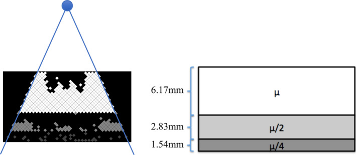
Figure 1.

Two‐dimensional schematic diagrams of the proposed FDBF: an example of the FDBF after its channels have been selectively filled (left) and the schematic of the three sections containing fluid with different attenuation coefficients (right) where is approximately 2.4 cm−1 for ZnBr2 solution and 1.9 cm−1 for GdCl3 solution. The blue circle represents an x‐ray source that produces fan‐beam radiation. Note that the gray scale values shown in the FDBF are proportional to the relative attenuation coefficient in the channel. [Color figure can be viewed at wileyonlinelibrary.com]
