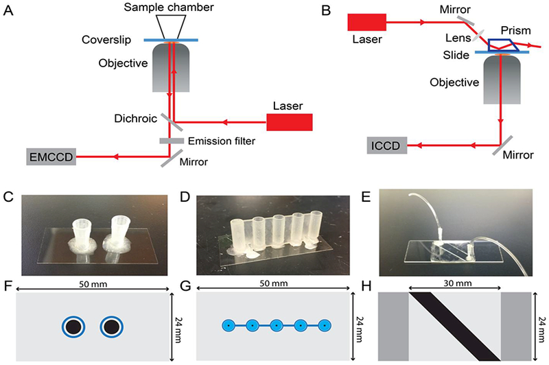
Fig. 2.

Overview of instrumentation and sample cells. (A) Objective-type TIRF microscope. (B) Prism-type TIRF microscope. (C) Pipet tip chamber sample cell. (D) 3D-printed sample cell with cylindrical reservoir and tapered conical base. (E) Sandwich-type sample cell for prism-TIRF measurements. (F)-(G) Scale drawings showing a top view of each sample cell type shown in (C)-(E). The black-shaded region in each panel represents the surface area available for target capture and imaging on the coverslip or slide. Blue-shaded regions in (F) and (G) represent the plastic walls of the sample wells.
