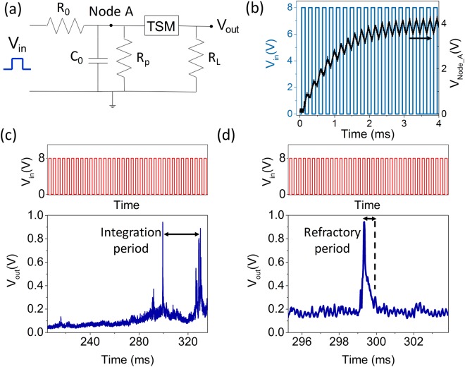
Figure 4.
(a) Schematic of the circuit used to realize the artificial neuron. (b) Input voltage pulses and voltage at node A as a function of time. When a series of voltage pulses of an amplitude of 8 V with TON = 100 µs (blue line) are applied as input to the circuit, the capacitor Co starts charging and the voltage at node A (black line) increases till the capacitor gets completely charged. (c) (Top) Input voltage pulses of amplitude 8 V, TON = 100 µs, frequency = 5 kHz (not to scale). (Bottom) Output spike of the artificial neuron showing the integration time. (d) (Top) Input voltage pulses of amplitude 8 V, TON = 100 µs, frequency = 5 kHz (not to scale). (Bottom) Output spike of the artificial neuron showing the refractory period of the neuron.

