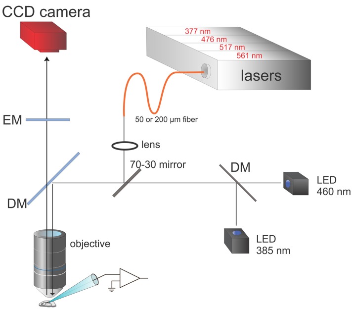
Figure 3.
Schematic of modified apparatus including both LEDs and lasers. The box at the top contains four lasers at the indicated wavelengths. The laser outputs, which can be separately controlled, are combined and focused onto either a 50 μm or 200 μm diameter fiber optic. The face of the fiber is focused with a lens and the objective onto a region of the slice, after 30% of the light is reflected off a mirror in the microscope body and a special DM in a standard filter cube (see Figure 1B for a typical filter set). The LED outputs are combined and 70% of the light passes through to preparation. Software selects combinations of LEDs and lasers to excite the indicator dyes in the cell of interest. The CCD camera (RedShirtImaging, NeuroCCD-SMQ) detects the fluorescence changes with frames synchronized with the laser or LED pulses.

