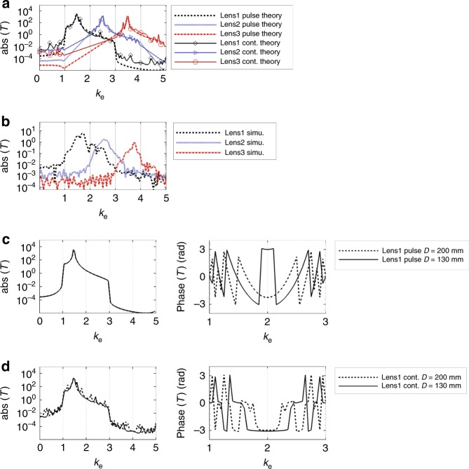
Fig. 4.
Transmission properties of the whole system. a Amplitudes of theoretically calculated image transfer functions of lens1, lens2 and lens3 for pulse source case and continuous source case. Lens1, lens2 and lens3 correspond to systems that work for wave vectors in ke ∈ [1, 2], [2, 3], and [3, 4], respectively. b Amplitudes of simulated image transfer function of lens1, lens2 and lens3. Simulation is performed in frequency domain, taking into consideration the multiple reflections between gratings. c When using continuous source, theoretically calculated amplitudes and phases of image transfer functions for lens1 when D = 130 mm and D = 200 mm. D is the distance between the transmitter and the receiver. d When using pulse source, theoretically calculated amplitudes and phases of image transfer functions for lens1 when D = 130 mm and D = 200 mm

