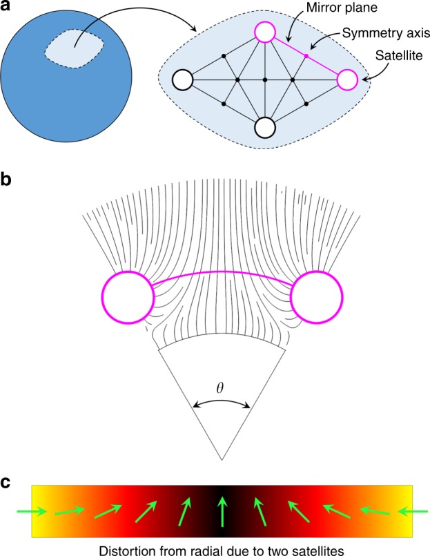
Fig. 2.

Satellite distortion network. a Sub-domain of the spherical surface corresponding to the primary satellite orbit. Large unfilled circles represent satellites, small filled circles represent symmetry axes of rotation with radial director profiles and solid lines represent unfolded mirror planes. The plane of highest disturbance (repeated in the structure) is highlighted in magenta. b A slice of the magenta plane from a, showing the director streamlines due to two satellites separated by a polar angle of θ. c Distortion of the director field in the radial reference frame as a function of the polar angle between two neighboring satellites along their orbital path, magenta arc from b
