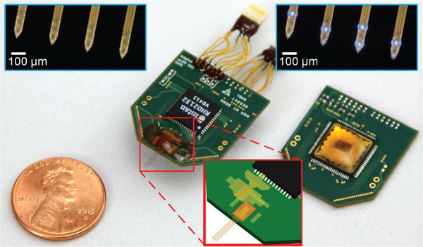
Fig. 7.
Photographs of the assembled headstages. Insets show (top) microphotographies of the tips of the optoelectrodes, and (bottom) the schematic diagram of the polyimide-based flexible cable interposer. The light leakage from the sides of the optoelectrode shank, shown in the top right inset, is an artifact due to the combination of poor light coupling efficiency in the air and high optical output power. Modified from [20].

