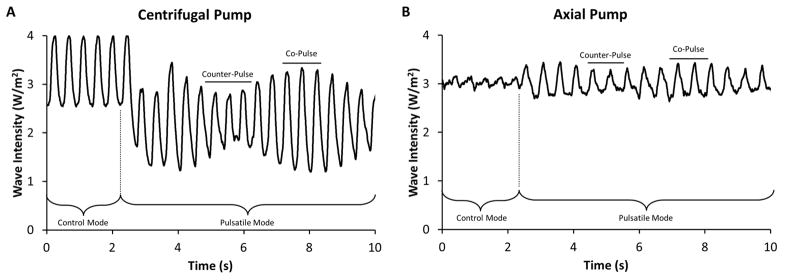
Figure 3. LVAD outflow patterns during control and asynchronous pulsatile operation.
The different LVAD outflow patterns for the centrifugal pump (Panel A) and the axial pump (Panel B) are shown during the initial transition between control and pulsatile modes of operation. The difference between the intrinsic heart rate and pulsatile LVAD rate result in the amplitude changes of pump flow. Co-pulse is identified by the individual cardiac cycles with high amplitude and counter-pulse is identified by the individual cardiac cycles with low amplitude.

