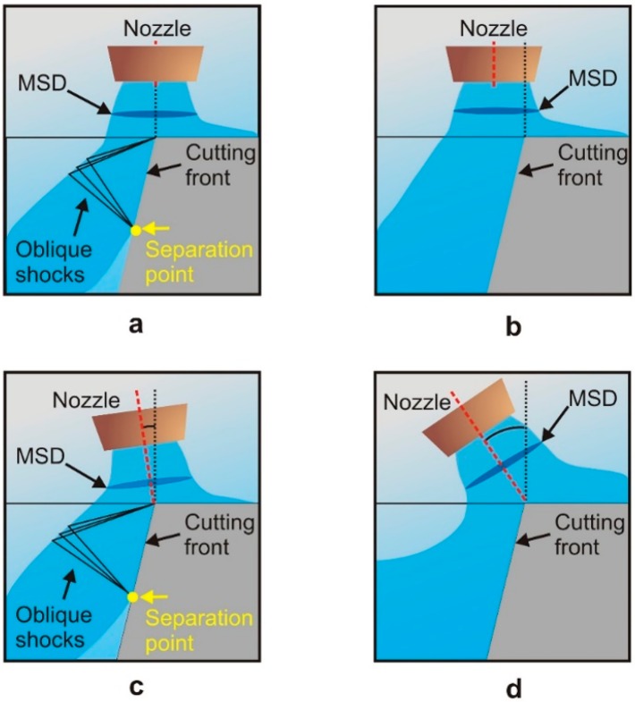
Figure 18.
A schematic view of the aerodynamic interactions for (a,b) different nozzle positions, and (c,d) different nozzle tilt angles. The arrow in (a) and (c) denotes the boundary layer separation. Adapted with permission from [89]; Copyright 1997 AIP Publishing.

