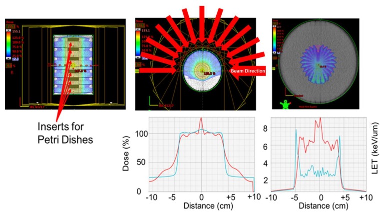
Figure 5.
Geometry used to irradiate the cells with 0.5 and 0.25 Gy of protons, while maximizing the LET within the petri dishes. Top-left: CT image cross-section of the cylindrical phantom. The phantom is composed of six individual blocks made of solid water. Solid water phantoms are made of epoxy resins and powders to control density and radiation properties of the phantom and are traditionally used for dosimetry purposes. Each block was of 200 mm in diameter and 30 mm in depth. The blocks had a 60 mm insert centered in the central axis of the block, where the petri dishes were placed for the exposure. Each proton beam used had a vertical extension beyond the petri dish holder. Top-center: Color-wash of the proton dose distribution produced by 13 concentric and co-planar proton beams of 101 mm range. The 13 beams were delivered over an arc of 180 degrees and were separated every 15 degrees. Each beam only used a single energy of 117.14 MeV. Top-right: color-wash figure showing the Linear Energy Transfer distribution of the beam arrangement use. The image shows the LET increase at the distal falloff of each beam. Bottom-left: dose profile across the central plane of the cylinder (red line). The dose coverage extended 1 cm beyond the edges of the inserts to ensure the dishes received 100% of the dose. The blue line represents the dose profile that would be obtained if the beams had a Spread of Bragg Peak (SOBP), which improves the homogeneity of the dose. Bottom-right: Profile of the LET distribution across the target. The LET using the monoenergetic beams is higher within the Petri dishes, compared with the SOBP beams.

