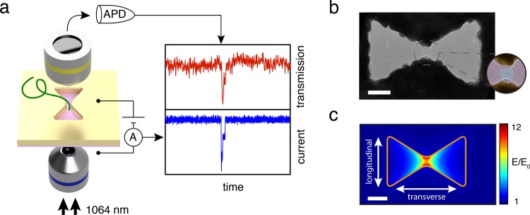
Figure 1.
Inverted-bowtie plasmonic nanopore. (a) Schematic of the plasmonic nanopore experimental setup. (b) Transmission electron microscope (TEM) image of a plasmonic inverted-bowtie with a nanopore drilled in its gap. The zoom shows a false-colored TEM image of the nanopore in the gap. (c) Normalized electric-field density distribution simulated for the idealized geometry (outlined in orange) of the nanoantenna in (b), clearly revealing optical-field localization and field enhancement up to 12 times in the gap region of the antenna. Scale bars are 50 nm.

