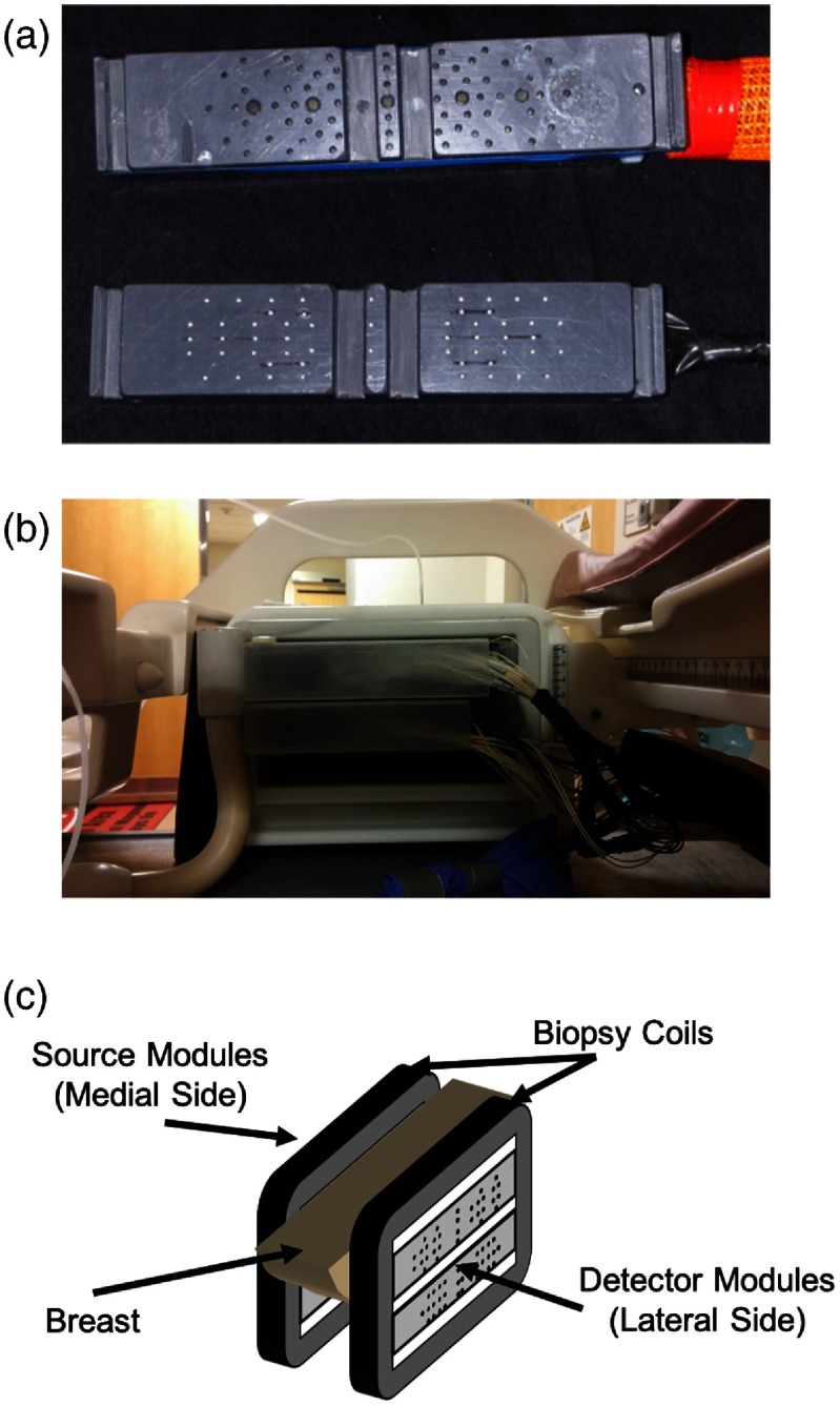
Fig. 3.
Optical source and detector modules. (a) Front view of one detector module (top) and one source module (bottom). On the detector module, the large fiber tips are the 3-mm fibers coupled to PMTs, and the smaller tips are either the 1-mm fibers imaged onto the CCD or DCS source fibers. The fiber tips on the source modules are either source fibers coupled to the optical position switch or single-mode DCS detection fibers. (b) A rear view of the source modules in the breast biopsy coil. (c) Schematic of the optical modules within the breast biopsy coil windows in a sagittal parallel-plate configuration on both sides of the breast. Note that the source modules (medial side) and the detector modules (lateral side) can be moved vertically within the biopsy window to ensure coverage of the tumor region of the breast.

