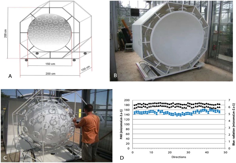
Fig 2. Isotropic light device.
A: 3D quoted scheme of the isotropic light device. B: View of one hemisphere showing the turtle pattern of circular neon tubes at the periphery of the white plastic hemisphere. C: View of one hemisphere covered with metallic plates to concentrate the lighting towards the inside of the hemisphere. D: Measurements of PAR and blue radiation in the two spheres in 46 directions with an optic fiber mounted on a robot set in the center of the sphere. Black symbols: PAR; blue symbols: blue radiation.

