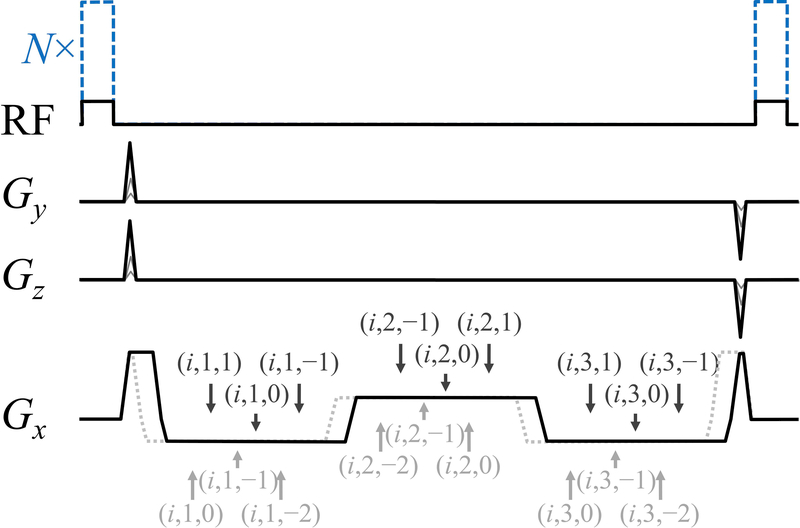
Fig. 1.
: A three-pathway three-echo version of our MPME sequence is depicted here. Using a (i, j, k) notation to represent the jth echo from the kth pathway during the ith scan, the timing of all pathway and echo acquisitions is displayed with arrows, for two acquisition scenarios: [1,0,−1] (solid black line in Gx channel) and [0,−1,−2] (dotted gray line). In the RF channel, black lines indicate the smaller flip angle acquisition, i=1, while dashed blue lines indicate the larger flip angle acquisition, i=2. Only three of these magnetization states are needed for the proposed processing to be carried out, which explains why either a [0,−1,−2] or a [1,0,−1] scheme can be chosen.

