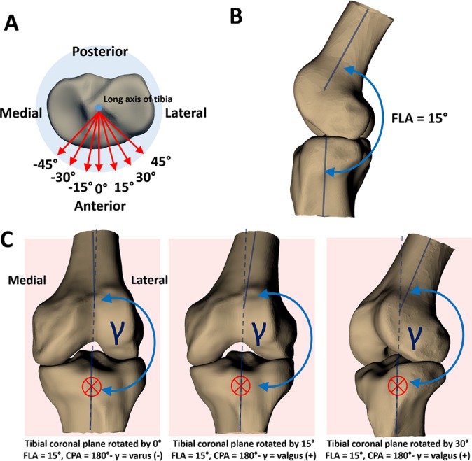
Figure 3.

(A) The blue dot in the center of the tibial plateau represents the long axis of the tibia oriented perpendicular to the page. The red arrows represent the tibial anteroposterior axis, rotated by viewing angles of –45° to 45° in increments of 15°. These anteroposterior axes represent the unit-normal vectors to the coronal planes in which coronal plane angles (CPAs) are measured. The viewing angle of 0° represents a measurement of the CPA in the plane defined by the unrotated unit-normal vector of the tibial coronal plane (representing an anterior or posterior coronal view of the joint)—a best-case scenario for measuring knee abduction angle from 2D video frames. (B) The knee positioned at a flexion angle (FLA) of 15°. (C) Changing the viewing angle (rotating the anteroposterior axis that defines the tibial coronal plane) changes the CPA. The red crosses denote the coronal plane, oriented perpendicular to the page, and the dashed blue line represents the long axis of the tibia extended into the femur for reference. At a viewing angle of 0°, CPA is negative, indicating varus alignment. However, at a viewing angle of 15°, CPA is positive, indicating a valgus alignment. As viewing angle increases, alignment appears more valgus. The FLA is 15° in all of these scenarios; this effect would be more pronounced when the knee is positioned in more flexion.
