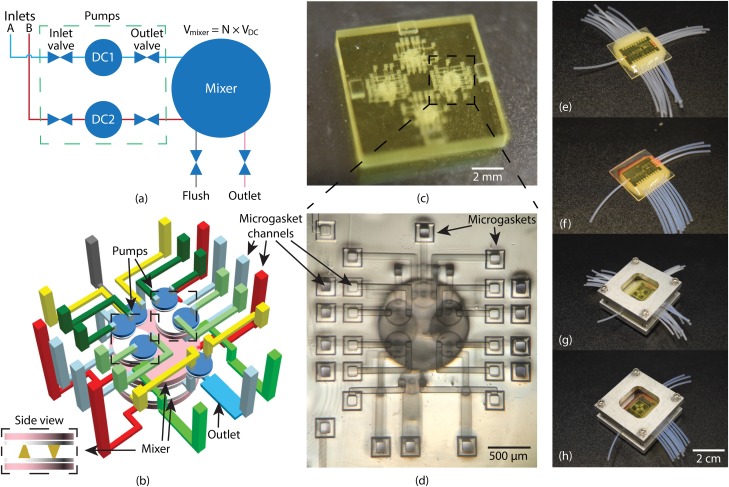
FIG. 3.
(a) Schematic of LDMP. It contains 2 pumps which are connected to a fluid reservoir. They can selectively pump fluid to the mixer which performs mixing. (b) 3D layout of (a). Pumps are stacked on top of the mixer, and the mixer has 2 large DCs connected to each other via cone-shaped channels. (c) Photograph of a 3D printed device designed for characterization of 4 LDMPs on a single chip. (d) Microscope photo of an LDMP which uses microgaskets developed in Ref. 5. (e) LDMP flushing chip. (f) LDMP operation chip. (g) LDMP device chip assembled with flushing chip. (h) LDMP device chip assembled with operation chip.

