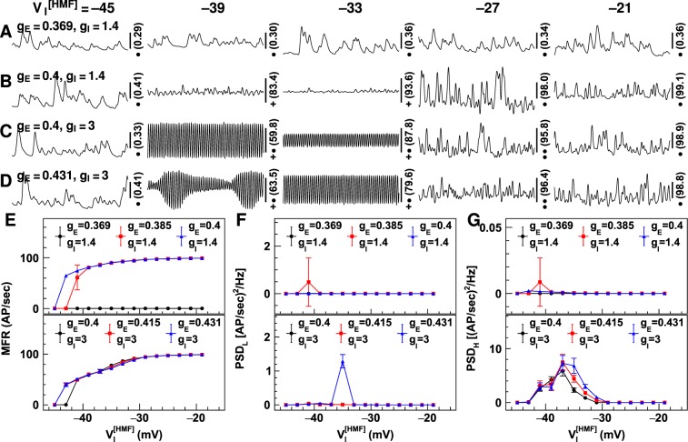
Figure 8.
Neuronal firing rates simulated using positively shifted firing thresholds of inhibitory neuron groups. Shown are the neuronal firing rates simulated using positively shifted voltage at half-maximum firing (). Figures (A–D) display the firing rates obtained using four synaptic gain combinations. The synaptic gain values are shown on the left [unit: uV/(mV · Hz)], and the values for are shown on the top (unit: mV). The number on the right is the firing rate in the middle of the vertical scale bar (unit: AP/sec), and the markers indicate the values of vertical scale bars: •−0.1 AP/sec; ••−0.5 AP/sec; +−5 AP/sec; +•−25 AP/sec. The horizontal scale bars represent a 200 millisecond period. Figures (E–G) display the temporal mean firing rates (MFR; (E)), and power spectrum density for firing rates of 2–15 Hz (PSDL; (F)) and 16–50 Hz (PSDH; (G)) using different synaptic gains. Synaptic gain values are displayed at the top [unit: uV/(mV · Hz)]. Error bars represent the standard deviation for 10 runs of the LCM using the same parameter values but different random number kernels.

