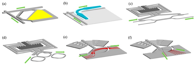
Figure 4.
Schematic of (a) a switch based on vertically MEMS-actuated directional waveguide coupler (b) a switch based on vertically MEMS-actuated adiabatic waveguide coupler (c) a switch based on laterally MEMS-actuated directional waveguide coupler (d) a switch based on laterally MEMS-actuated MRR (e,f) a switch based on rotationally MEMS-actuated waveguide.

