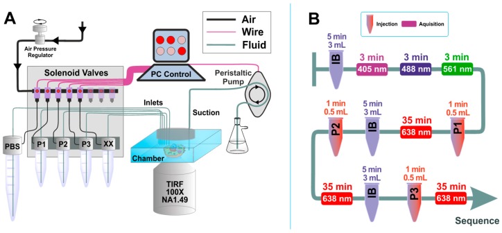
Figure 3.
Scheme of custom-built microfluidics setup and Exchange PAINT experiment. (A) Microfluidics setup: The setup is controlled by a computer software, which includes both manual and automated operation modes. Maximum number of the input channels is 24 (only 5 channels are shown). The peristaltic pump used to remove the solutions from the chamber is also computer-controlled. (B) Typical sequence of actions for the Exchange PAINT experiment. The tube-shape sketches depict the injection of solutions (P1, P2, or P3) or the imaging buffer (IB) (solution volume and injection duration are indicated on top of the objects). Rectangles represent movie acquisition with certain laser excitation (laser wavelength and total acquisition time are indicated inside the rectangle and on top of the rectangle, respectively).

