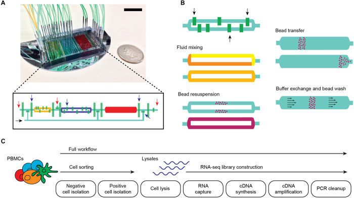
Fig. 1. Microfluidic chip design and integrated workflows.
(A) Photograph of a 10-channel chip filled with yellow, blue, and red dye to highlight compartments; control valves are filled with green dye. Scale bar, 2 cm. The inset shows the diagram of one channel, where compartments and control lines are colored similar to the photograph. Red and black arrows indicate sample input/output and reagent input ports, respectively. Blue arrows indicate control valves that control flow through the channels. (B) Schematic showing key device capabilities that enable various sample preparation steps. Black arrows indicate mixing valves that alternately open and close to generate flow within a compartment, allowing for reagent mixing and bead resuspension without external fluid input. Permanent magnets are used for moving magnetic beads across different compartments or preventing their flow during buffer exchange and washes. (C) Full and partial (cell sorting and RNA-seq) sample preparation workflows implemented in the microfluidic chip.

