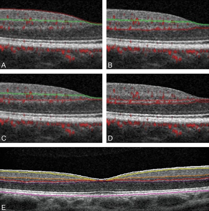
Fig. 1.

Boundaries of retinal vascular plexuses and retinal layer segmentation. Optical coherence tomography B-scans with angio-flow showing the retinal segmentation in the different capillary plexuses (top and middle) and the segmentation of the retinal layers (bottom). A. B-scan showing the boundaries (red and green lines) that delineate the SVP between the ILM and 9 µm above the junction between the IPL–INL. B. B-scan showing the boundaries (green and red lines) that delineate the DVC between 9 µm above the IPL–INL junction and 9 µm below the OPL–ONL; there is no overlap between the 2 previous slabs. C. B-scan showing the boundaries (green and red lines) that delineate the ICP between 9 µm above the IPL–INL junction and 6 µm below the INL–OPL junction, thus including parts of the IPL and OPL and all the INL. D. B-scan showing the boundaries (red lines) that delineate the DCP between 6 µm below the INL–OPL junction and 9 µm below the OPL–ONL junction, thus including the OPL. E. B-scan showing the retinal layer segmentation provided by AngioAnalytic software. From the inner retina to the outer retina: white line (ILM), yellow line (outer boundary of the nerve fiber layer), orange line (outer boundary of the IPL), red line (outer boundary of the INL), violet line (outer boundary of the OPL), and purple line (outer boundary of the retinal pigment epithelium).
