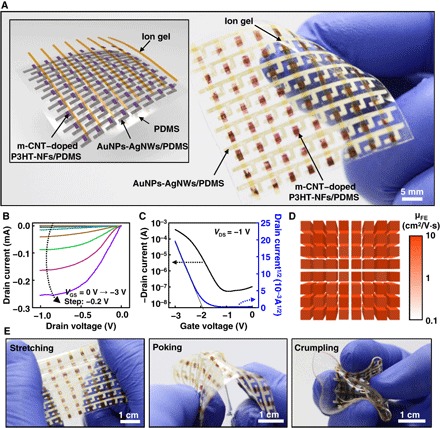
Fig. 2. Rubbery transistors array.

(A) An optical image of the fabricated high-performance rubbery transistors array. Inset is the exploded schematic view. (B) Representative output characteristics of the m-CNT–doped rubbery transistors. (C) Representative transfer characteristics of the m-CNT–doped rubbery transistors. (D) Calculated μFE map of the 8 by 8 transistor array. (E) Transistor arrays under different mechanical deformation modes.
