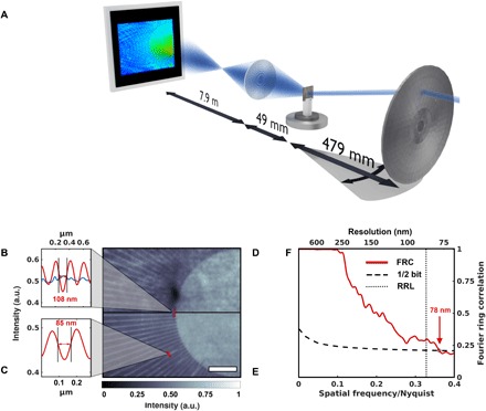
Fig. 1. X-ray Fourier ptychography by scanning the illumination direction.

(A) A sketch of the experimental setup. By inserting a movable pinhole (not shown) close to the fixed condenser, a standard TXM setup can be modified for Fourier ptychography as the change in illumination direction can be achieved by selecting individual subfields of the condenser. (B to E) A comparison of the flat-field corrected full-field image (D) and the magnitude of an x-ray Fourier ptychographic reconstruction (E) highlights the improvement in image quality and resolution. Scale bar, 2 μm. The test pattern’s last line cut indicates a linewidth of 150 nm, which is resolved with both techniques. Yet, the innermost lines, while being washed out in the full-field image, are resolved in the Fourier ptychographic reconstruction (B) (blue and red, respectively). Even smaller features with a width of 85 nm are visible in the Fourier ptychographic reconstruction (C). (F) A Fourier ring correlation (FRC) between two subsets of the Fourier ptychographic scan confirms the improvement in resolution. The dotted line marks the Rayleigh resolution limit (RRL).
