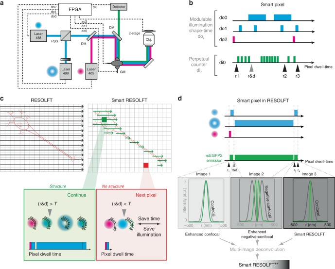
Fig. 1.
Smart pixel concept in RESOLFT imaging. a Hardware scheme of the smart RESOLFT sample-adaptive set-up. The field-programmable-gate-array card enables a rapid feedback loop between illumination, detection and scanning system. Multiple illumination lines, up to five digital outputs doi modulate up to five illuminations, which can change in shape and/or colors. The control software/hardware named Carma syncronizes the scanning architecture and the illuminations with three different analog output aoi, and with the photon detection device di1. b Schematic illustration of the flexible illumination and signal registration of Carma. The combination of real-time adaptive illumination and time binned detection is named smart pixel since it is applied on the very same sample region. The number and the duration of the illumination pulses and the width of signal classification windows can be flexibly adjusted. In particular, Carma implements a perpetual counter that is initialized at the start of the smart-pixel. Up to five different read-out points ri can be introduced within the deterministic pixel-dwell time. By calculating the difference between two consecutive read-out windows, it is possible to classify the photons collected under a specific illumination. The read-out points coincide with the activation/deactivation of the laser beams. The read-out window named r&d is introduced to implement the threshold-based detection for the real-time feedback system. c Raster (left) compared to smart (right) scanning, which is specimen-adaptive. The feedback loop and smart pixel technologies enable to perform RESOLFT imaging only in regions of the specimen containing labeled structures. The decision in smart RESOLFT (red and green boxes) is performed intra-pixel and it is threshold based. d Smart pixel in RESOLFT. The fluorescence photons are classified in three separated detection windows corresponding to the probing, doughnut (OFF-switching) and read-out illumination. In conventional RESOLFT only the windows corresponding to the read-out illumination (r4−r3) is recorded. Here, we combine the signal generated by the three windows through a multi-image deconvolution to generate an image of higher quality. RESOLFT REversible Saturable/Switchable Optical Linear Fluorescence Transitions

