Fig. 2.
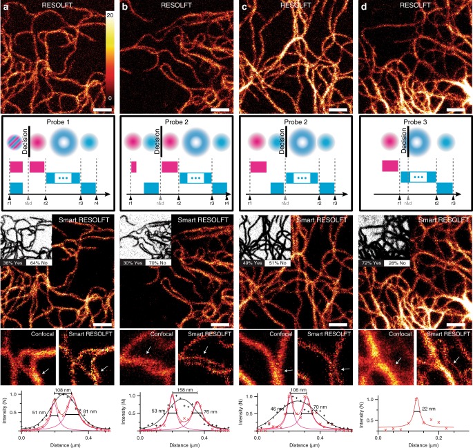
Probe types and decision-making in smart RESOLFT imaging. a−d In the top row conventional RESOLFT images of vimentin-rsEGFP2 are shown. By applying the smart RESOLFT illumination schemes illustrated below each image, we acquired a second image in the smart RESOLFT mode. The insets in the smart RESOLFT images represent the decision map containing the skipped pixels (white, NO), and the ones that undergo the full pulsing scheme (black, YES). For each smart RESOLFT image we provide a zoom of a small region, the related confocal image and a line profile (white arrow) for comparison. Each line profile is averaged across three pixels, and the full-width at half-maximum and peak-to-peak distance of Lorentzian fits is shown in the line profile. Scale bars are 1 µm, the zoom region is 1.5 by 1.5 µm2. RESOLFT REversible Saturable/Switchable Optical Linear Fluorescence Transitions

