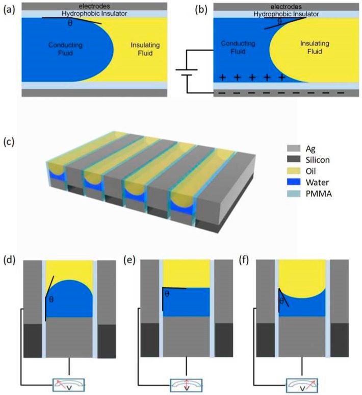
Figure 1.
The principle of electrowetting is shown in (a,b). (a) The initial state and (b) indicates the situation after applying voltage. (c) The sketch of the model we created. In the figure, gray, black, yellow, blue and transparent areas respectively represent metallic silver, silicon elemental, oil, water and medium polymethyl methacrylate (PMMA). (d–f) The three different cases of the interface morphology after voltage application.

