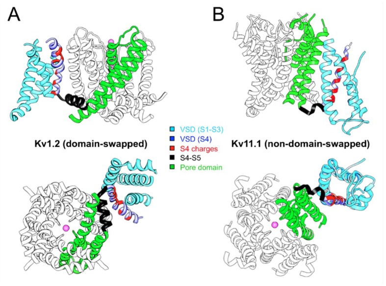
Figure 1.
Comparison of domain-swapped (A) and non-domain-swapped (B) architectures of Kv channel transmembrane domains. Only a single VSD is shown attached to the tetramer of the PD for clarity. One complete subunit is shown colored as indicated. The magenta balls indicate the position of K+ ions in the selectivity filter. Note the different length of the S4–S5 linker determining the VSD contact with the neighboring (A) or the same (B) subunit. Structures viewed from the membrane plane (top) and from the cytoplasmic side (bottom) are shown for Kv1.2 (PDB: 2A79) and Kv11.1 (hERG, PDB: 5VA2).

