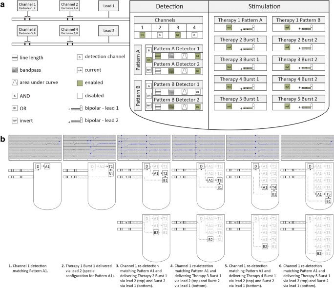
Fig. 2.
(A) Simplified representation of RNS System detection and stimulation parameters with sample configuration. Icons represent configurable groups of configurable settings. Highlighted icons (green) represent a sample of enabled settings. Hardware. Two depth electrodes (leads 1 and 2) are connected to a programmable processor. Detection. Detection is enabled for channels 1 and 2. Pattern A1 is enabled with a line length detector to trigger when a detection occurs on channel 1. Pattern A2 is enabled with a bandpass detector to trigger when a detection occurs on channel 2. Pattern A triggers when Pattern A Detector 1 or Pattern A Detector 2 trigger. Pattern B2 is enabled with a bandpass detector to trigger when a detection occurs on either channel 2. Pattern B1 is disabled. Stimulation. Therapy 1 only is configured with different response for Pattern A versus Pattern B. The montage is configured in bipolar fashion to deliver subsequent therapy in bursts that alternate between lead 1 and lead 2. (B) Closed-loop sequence of events. This sequence of events shows how the sample configuration (see Fig. 1) responds to monitored brain activity. Each ECoG snippet (top) represents activity that corresponds with a schematic (middle) and description (below). Detection (D) occurs, followed by a therapy (T) comprised of up to two bursts (B). Each subsequent therapy is contingent upon re-detection and represents a closed-loop; two bursts may occur for a single re-detection

