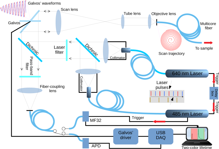
Fig. 1.
Optics diagram and block diagram of the laser-scanning endomicroscope. A USB controlled DAQ generates the scanning waveforms and acquires the analog signal from the APD when in pure intensity scanning mode. The MF32 camera for FLIM data acquisition is controlled through a separate USB interface. Center right shows the trigger signal path originating in the 640 nm laser, passing through a delay box, triggering the 485 nm laser and finally triggering the MF32 camera. The emission dichroic and excitation filters are the XF454 set from Horiba. The schematic shows a raw histogram as acquired from the MF32 camera, showing the red fluorescence decay and the temporally shifted green fluorescence decay (bottom right).

