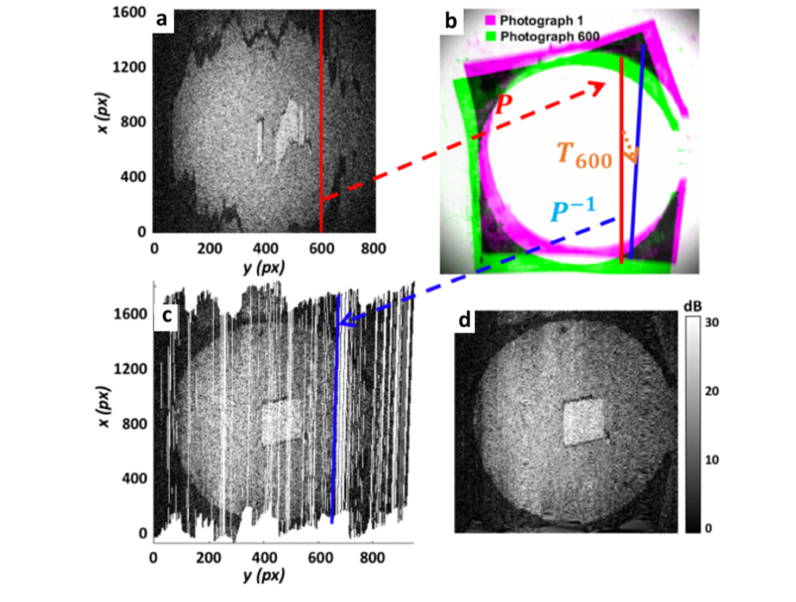
Fig. 4.
Illustration demonstrating the motion correction technique. (a) B-scan 600 is selected to demonstrate transformations applied to motion-correct its position. (b) It is first transformed to its lateral position in Photograph 600, shown in green, then mapped its co-registered position in Photograph 1, shown in purple, using T600. (c) Finally, this is mapped back to its corresponding OCT coordinate location, now motion-corrected. Mapping all B-scans in this way, with their associated co-registration transformation (), generates the underlying en face OCT scatterplot shown. 2D interpolation and cropping of this scatterplot generates the final output motion-corrected en face OCT image in (d).

