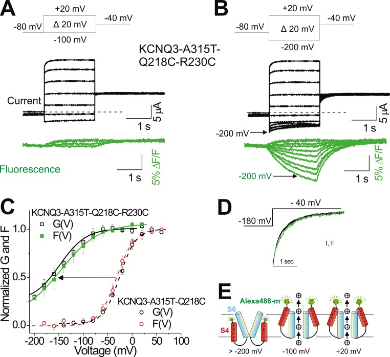
Figure 2.
R230C shifts the voltage sensor movement and gate closing of KCNQ3 channels to very negative voltages. (A and B) Representative current (black) and fluorescence (green) traces from labeled KCNQ3-A315T-Q218C bearing R230C mutation for the indicated voltage protocols. In response to voltage steps more negative than −100 mV, R230C channels started to close and reopen when stepped back to −40 mV. Dashed lines represent zero current. (C) Extrapolated tail conductance (black) and fluorescence (green) from B were normalized (see Materials and methods) and plotted versus test voltages (G(V) and F(V) of KCNQ3-A315T-Q218C-R230C, black and green squares, respectively; means ± SEM, n = 9). The tail conductance (black) and fluorescence (red) of KCNQ3-A315T-Q218C are shown for comparison. Lines represent the fitted theoretical voltage dependencies (see Materials and methods, Eqs. 1 and 2). (D) Comparison of activation kinetics of current (black) and fluorescence (green) signals from KCNQ3-A315T-Q218C-R230C in response to the voltage protocol shown. (E) Cartoon representing a model of KCNQ3-A315T-Q218C-R230C channel gating where the equilibrium of the S4 movement is shifted to very negative voltages so that at −100 mV, S4 is in the activated position, allowing channel opening. S4 (red), S6 (blue), and Alexa Fluor 488 (green). For simplicity, only two of the four subunits in the tetrameric channel are shown.

