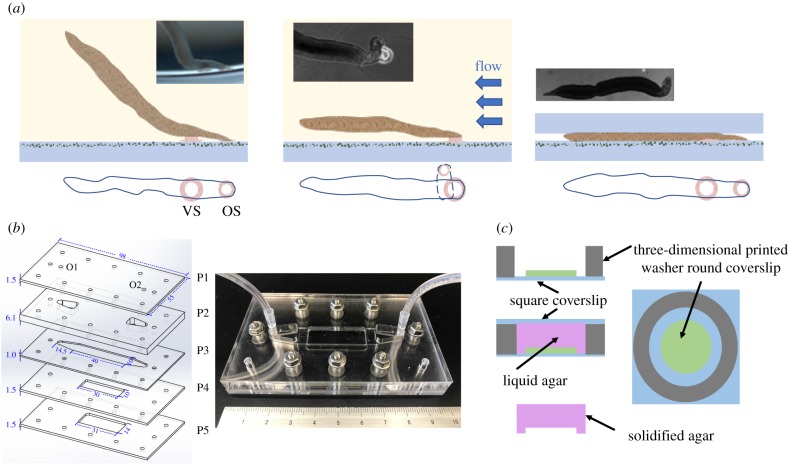
Figure 1.
Overview of various experimental designs to model the mechanical environment of S. mansoni. (a) Schematics of a free adhesive (sucker-based) locomotion (left), a worm adhering against flow (centre), and a worm moving under confinement (right), with corresponding bright-field images (left, lateral view; centre and right, dorsal views) captured during our experiments. VS and OS refer to the ventral and oral suckers, respectively. (b) Flow chamber design. The image to the left illustrates the device's layered design with the important dimensions indicated in millimetres. O1 and O2 are inlet and outlet orifices. The image to the right is a photograph of the assembled device. (c) Fabrication scheme of the agar cap system used to generate controlled confinement. A three-dimensional printed PLA washer (grey) and a round coverslip (green) are glued onto a square coverslip (blue). An agar solution (purple) is poured and covered with a square coverslip to flatten its surface while the solution solidifies. Varying the number of round coverslips controls the gap produced in the agar gel. (Online version in colour.)

